
In the world of electronic product development, a “working prototype” is only the first 10% of the journey. For B2B companies and hardware startups, the real challenge lies in selecting an architecture that is not only functional but manufacturable at scale.
Whether you are an ECE student preparing for an interview or a product manager vetting a Bill of Materials (BOM), here is the essential breakdown of the core components of an embedded system—viewed through the lens of manufacturing and reliability.
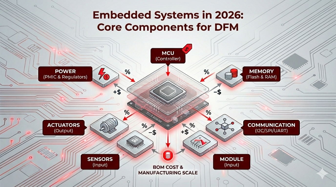
1. The Controller: MCU vs. MPU
The “brain” of your system dictates your entire power budget and PCB complexity.
- Microcontrollers (MCU): An all-in-one chip containing the CPU, RAM, and Flash. These are the gold standard for IoT and medical devices due to low power consumption and simplified layouts.
- Microprocessors (MPU): Feature a powerful CPU but require external memory and peripherals. Use these only if your product requires a heavy OS (like Linux) or complex graphical interfaces.
The 2026 Reality: While high-end AI chips grab headlines, the 2026 semiconductor outlook highlights that “mature node” semiconductors remain the backbone of global production. When picking a chip, availability is now as vital as clock speed.
Titoma Tip: For a deeper dive into silicon selection, see our comparison on STM32 vs PIC32 for manufacturing.
2. Memory Architecture (RAM, ROM, Flash)
Embedded memory is about more than just capacity; it’s about persistence and speed.
- Flash (Non-volatile): This is where your firmware lives. Pro Tip: Always over-spec your Flash by 30-50% to allow for Over-the-Air (OTA) updates. A product that cannot be updated in the field is a liability.
- RAM (Volatile): Temporary workspace. As Edge AI and TinyML become the norm in 2026, your RAM requirements will likely spike to handle on-device intelligence.
3. Communication: I2C, SPI, and UART
These protocols are the “digital dialogue” between your chips. Your choice here directly impacts your PCB trace density.
| Protocol | Pins | Speed | Best For… |
| UART | 2 | Low | Debugging and simple GPS/LTE modules. |
| I2C | 2 | Medium | Low-speed sensors (saves valuable PCB space). |
| SPI | 4+ | High | High-speed data like Displays and External Flash. |
For a technical breakdown of performance trade-offs, this comparative analysis of UART, SPI, and I2C provides excellent academic data for your design phase.
4. Sensors & Actuators (The I/O)
- Sensors: Convert the physical world (heat, motion, light) into digital bits.
- Actuators: Turn those bits back into physical action (motors, relays, LEDs).
The Titoma perspective: Always prioritize “second-source” parts for these components. If you design around a unique, proprietary sensor and that supplier goes on a 50-week lead time, your production line stops. We see these kinds of BOM surprises and DFM mistakes sink projects every day.
5. Power Management
Hardware failures rarely happen in the code; they happen in the power stage. A professional embedded system needs a clean, regulated voltage. Whether you’re using an LDO or a high-efficiency Buck Converter, your circuit must be robust enough to handle electrical noise—especially in industrial environments.
The “Real World” Check
Hardware is a game of trade-offs between cost, power, and performance. The best engineers don’t build the most complex system; they build the one that can be manufactured reliably at scale.
For a full breakdown of how to optimize your project for the factory floor, see our complete guide to DFM for electronics.