
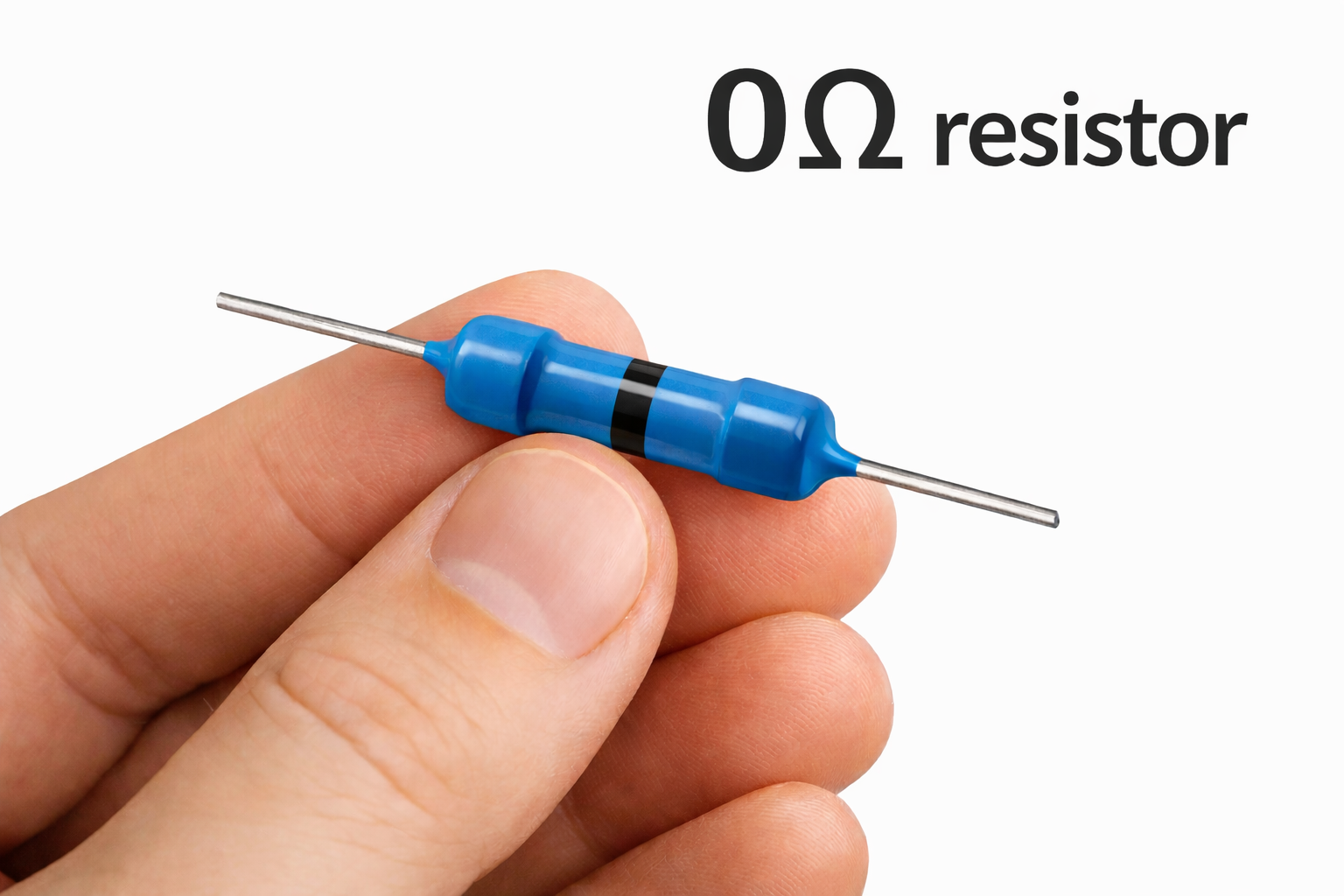
A zero-ohm (0Ω) resistor looks like a joke component.
If it acts like a short, why not just use a trace and move on?
Because in real PCB design, a 0Ω resistor is not there to impress anyone. It is there because it solves small, annoying, expensive problems in a clean way. That is why it keeps showing up on industrial boards, production hardware, and prototypes that later need to scale.
It may look trivial on the schematic. On the board, it often earns its place.
It gives engineers flexibility without making the board messy
One of the most common uses is as a jumper.
A 0Ω resistor lets engineers keep routing options open, support small layout changes, or maintain one PCB across multiple product versions. Instead of hard committing everything into copper from the first spin, the board gets a little breathing room.
That flexibility matters more than people think. A small placeholder can save a redesign, or at least make one less painful.
A 0Ω resistor also makes more sense when you look at the board as a production object, not just a schematic. That is close to the point Titoma makes in 10 Commonly Used PCB Components Explained, where simple looking parts can still create outsized problems in yield, sourcing, EMI, and long term reliability if they are chosen casually.
It fits normal SMT assembly better than a wire link
This is one of the least glamorous reasons, which usually means it is one of the most important.
A 0Ω resistor can go through standard pick and place, reflow, inspection, and rework. A hand soldered wire cannot. In a lab, that may seem like a minor detail. In production, it becomes the difference between a tidy process and a workaround nobody wants to own.
That is why 0Ω resistors are often preferred over manual jumpers even when both would do the same electrical job.
The assembly side matters too. A jumper that fits normal SMT flow is easier to place, inspect, and rework than an improvised wire link, which is exactly the kind of issue covered in 10 PCB DFM Rules Every Engineer Should Follow. In production, neat theory loses to parts that move cleanly through the line.
It helps during debugging
A 0Ω resistor is also useful when the board reaches bring up.
Placed in the right spot, it can be removed to isolate a section, break a loop, or make current measurement easier. That is much cleaner than cutting traces or bodging wires onto a board that already looks stressed enough.
This is one of those choices that feels unnecessary until the first debug session starts wasting hours. Then it suddenly looks very sensible.
A good real example comes from Texas Instruments’ LMP7721 evaluation board, where a 0Ω jumper resistor is used to connect the input path and support a specific board configuration. That is the practical value in one line. It is not there for style. It is there because a standard SMT part is cleaner than a manual link.
It can support cleaner ground strategy
Another reason designers use 0Ω resistors is to control where sections connect.
They may be placed between analog and digital ground areas, or between different parts of a grounding network, so engineers can tune or validate the connection point during testing. That does not fix a bad grounding scheme by itself, but it gives the team options before the layout is locked beyond easy adjustment.
Used properly, it is a controlled link. Used lazily, it is just a bandage over weak layout decisions.
Another real case appears in TI’s PHYTER design and layout guide, which recommends two size 1206 zero ohm resistors between chassis ground and system ground near the RJ-45. More importantly, those resistors can be removed or replaced during system level certification testing, which shows why 0Ω parts are useful as controlled connection points rather than just cheap shorts.
The package size matters more than people assume
This is where the part gets underestimated.
Many engineers casually treat 0Ω resistors as if they all behave like the same piece of wire. They do not. Their current handling depends heavily on package size, construction, copper around them, and how long the current is flowing.
That is why the smallest package is not always the smart choice. For light signal work, a small part may be fine. For heavier current or harsher industrial conditions, larger packages usually give better margin and lower risk.
Tiny parts look neat in CAD. Field failures look less elegant.
Bigger parts often make more sense in industrial products
In practical designs, many engineers prefer 0805, 1206, or larger packages when the resistor may carry meaningful current or face rougher operating conditions. The board loses a little space, but gains reliability, thermal margin, and easier rework.
That trade is often worth it.
The cost of a slightly larger part is usually small. The cost of a hot jumper buried inside a shipped product is not.
They also make sourcing easier
There is a supply chain reason these parts stay popular.
If a design team standardizes the same 0Ω resistor sizes and approved vendors across projects, inventory becomes simpler, purchasing gets cleaner, and substitution mistakes become less likely. That matters because these parts are supposed to remove friction, not create it.
A standard, common, easy to source 0Ω resistor is often more useful than the theoretically perfect one that complicates buying and assembly.
There is also a sourcing angle. Standardizing common 0Ω packages and approved vendors helps reduce procurement mistakes and keeps substitutions under control, which fits well with Titoma’s article on How to Build a Resilient BOM in 2025. A boring, widely available jumper is often more useful than a perfect one that creates supply friction.
They help with configurable boards too
0Ω resistors are also useful when one PCB needs to support small option changes.
That might mean enabling one feature for a premium version, changing a signal path, or making it easier to reconfigure the board without redesigning copper. It is a cheap way to keep a layout flexible while staying inside standard SMT assembly.
Microchip shows the same idea in its jumper options documentation, where a trace is cut and a 0603 zero ohm resistor is installed to switch board settings. That is a very normal production use case. The part acts as a configurable bridge that still fits standard assembly flow.
Why they keep surviving on real boards
0Ω resistors are still everywhere for one simple reason. They are practical.
They help with routing. They help with debugging. They support assembly. They can make validation easier. They can keep one board flexible enough for several variants. They are even sometimes used as placeholders where a fuse, filter, or optional feature may be added later.
None of that is flashy.
It is just good engineering discipline.
Final thought
A 0Ω resistor is one of those parts that looks pointless until you have worked on enough real boards.
Then it starts to look less like a fake resistor and more like a cheap insurance policy.
Used well, it gives the design team flexibility with very little penalty. Used carelessly, especially in the wrong package for the current, it becomes one more small mistake that should have been obvious earlier.
That is why so many PCBs still use them. Not because they are clever, but because they quietly solve problems.