

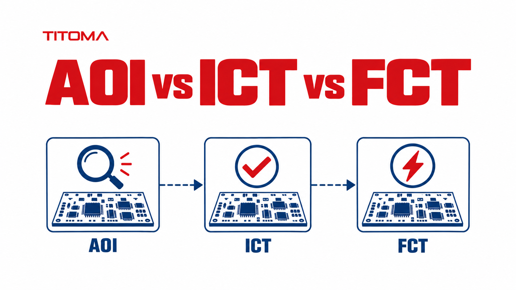
AOI (Automated Optical Inspection) checks a board visually for structural defects. ICT (In-Circuit Test) checks individual components and connections electrically. FCT (Functional Circuit Test) checks whether the finished board actually works. Each method catches a different category of defect, and most production boards need more than one.
AOI vs ICT vs FCT at a Glance
| Factor | AOI | ICT | FCT |
|---|---|---|---|
| What it checks | Visual and structural quality | Individual component and connection integrity | Overall functional behaviour |
| Method | Camera-based optical scan | Probes contact test points through a fixture or flying probe | Powers the board and applies operating stimuli |
| Catches | Missing or misaligned parts, solder bridges, polarity and placement errors | Shorts, opens, wrong values, and missing components | Firmware bugs, timing issues, and system-level interaction faults |
| Misses | Faults hidden beneath a component or outside camera view | Functional and firmware-level failures | Usually does not pinpoint the individual failed component |
| Best for | Fast first-pass inspection across production | Defect localisation and electrical coverage in stable builds | Boards whose real operating behaviour must be verified |
What Does Each Method Actually Catch?
AOI takes images of the PCB assembly and compares what it sees with a programmed reference. It is well suited to defects a camera can see: missing components, skewed placement, polarity marks, solder bridges, insufficient solder, and wrong component outlines. It is fast enough to sit directly in a production line, which is why it is often the first automated check after reflow.
AOI does not know whether a resistor is electrically correct just because the package looks right. It cannot see beneath a BGA or connector, and it cannot prove a circuit will operate. Its job is to identify visual process defects early, before a bad board consumes time at a later station.
ICT uses electrical probes to contact accessible nets on a populated board. A bed-of-nails fixture can contact many points together; a flying-probe system moves a smaller number of probes under software control. The tester measures expected values and connectivity, which makes it effective at finding shorts, opens, missing parts, wrong component values, and some orientation errors.
ICT produces more useful fault localisation than a functional test. If a measurement at a capacitor test point is out of tolerance, the technician has a place to start. The cost is access: the PCB needs suitable test points, board support, and a test program that accounts for parallel circuit paths. Those decisions need to happen while the board can still be changed without turning a small pad addition into a layout and fixture rework job.
FCT powers the board and checks the behaviour the customer actually cares about. Depending on the product, it may load firmware, exercise interfaces, verify analogue measurements, communicate with peripherals, or drive outputs under a controlled load. It is the only one of these three methods that can show whether the assembled board performs its intended task as a system.
FCT has a less tidy answer when something fails. A communication timeout may come from firmware, a connector, a wrong component, an assembly issue, or the fixture itself. That is why an FCT-only strategy can create a long debugging queue: it confirms the symptom but often leaves the cause to be found by investigation.
Why Do You Need More Than One Test Method?
These methods overlap at the edges, but they are not duplicates. AOI sees a solder bridge. ICT can measure the short that bridge created if the affected nets are accessible. FCT may report that the board will not boot. Each result points to a different part of the failure chain and gives the factory a different way to react.
| If you skip | Predictable gap | What tends to happen next |
|---|---|---|
| AOI | Visible placement and solder defects can reach electrical test | Later stations spend time diagnosing errors a camera could have found immediately |
| ICT | Component and net-level electrical faults are less isolated | Functional failures take longer to debug and repair |
| FCT | Firmware and real operating failures have no production check | A board can pass inspection and electrical checks but fail in the product |
A board can pass AOI with the correct-looking but wrong-value resistor installed. It can pass ICT if the circuit has no accessible way to distinguish that value under the configured test. It can then fail only when FCT applies the real operating condition. The inverse is also true: an FCT fault may be expensive to investigate when AOI or ICT coverage was omitted earlier in the process.
The aim is not maximum testing for its own sake. It is a test plan that matches the product’s risks, volume, and cost of field failure. For a safety-sensitive controller or a board that is expensive to service, the case for layered coverage is straightforward. For an early prototype, the same fixture investment may be premature, while a lighter test approach and engineering debug are more sensible.
What Test Strategy Fits Your Production Volume?
Early EVT builds change quickly. Engineers are still validating circuits, layouts, and firmware, so flexible methods such as visual inspection, flying probe, boundary scan where supported, and hands-on functional checks are often more useful than a dedicated ICT fixture. The main objective is learning where the design fails, not driving the lowest possible test time per board.
During DVT, test coverage should become more intentional. The product definition, enclosure, interfaces, and firmware are closer to their intended state. This is the point to confirm which nets need test access, whether the board needs added pads, and how a factory will handle known failure modes. The build gates in EVT, DVT, and PVT give a useful framework for making those decisions before the production release.
At PVT and into stable volume production, AOI provides repeatable process screening, and fixture-based ICT can reduce test time while finding electrical faults close to the assembly operation. FCT remains the final check that the programmed, assembled board behaves as the product requires. The exact mix varies by board, but the manufacturing partner should be able to explain why each station exists and what it covers.
High-volume production also changes the fixture calculation. A bed-of-nails fixture has an upfront cost, but a short cycle time can justify it when the design is stable and the quantity is high enough. A low-volume industrial board may be better served by flying probe plus targeted functional testing. Neither choice is a badge of quality on its own; the relevant question is whether coverage and throughput match the build.
How Does This Affect Your Manufacturing Partner Selection?
Ask a prospective EMS or ODM partner for a test flow, not a list of equipment. “We have AOI and ICT” does not say whether the quoted board will use either station, what the program measures, or how failed boards are handled. The useful answer names the station, coverage, exclusions, fixture approach, cycle time, and the route a board follows after a failure.
- Ask which defects AOI is programmed to check and whether inspection images are retained for traceability.
- Ask whether ICT will use a dedicated fixture or flying probe, which nets and parts are covered, and what is excluded.
- Ask what FCT powers, stimulates, and records, including firmware loading, communication checks, and output loads.
- Ask how test failures are logged, diagnosed, repaired, and retested before boards are released.
- Ask for the design-for-test review early enough that test-point access can be addressed through DFM, rather than after layout and tooling are fixed.
The IPC standards body publishes inspection and test standards that help define common expectations, but a standard name in a supplier presentation is not a coverage report. Ask what will be measured on your board. That small distinction separates an equipment list from a production test strategy.
At Titoma, the test plan is reviewed with the design and production teams before volume fixtures are committed. The practical output is a defined set of checks, clear handoffs between stations, and known exclusions that the customer can assess. A test plan should make the remaining risks visible, not hide them behind a pass label.
