

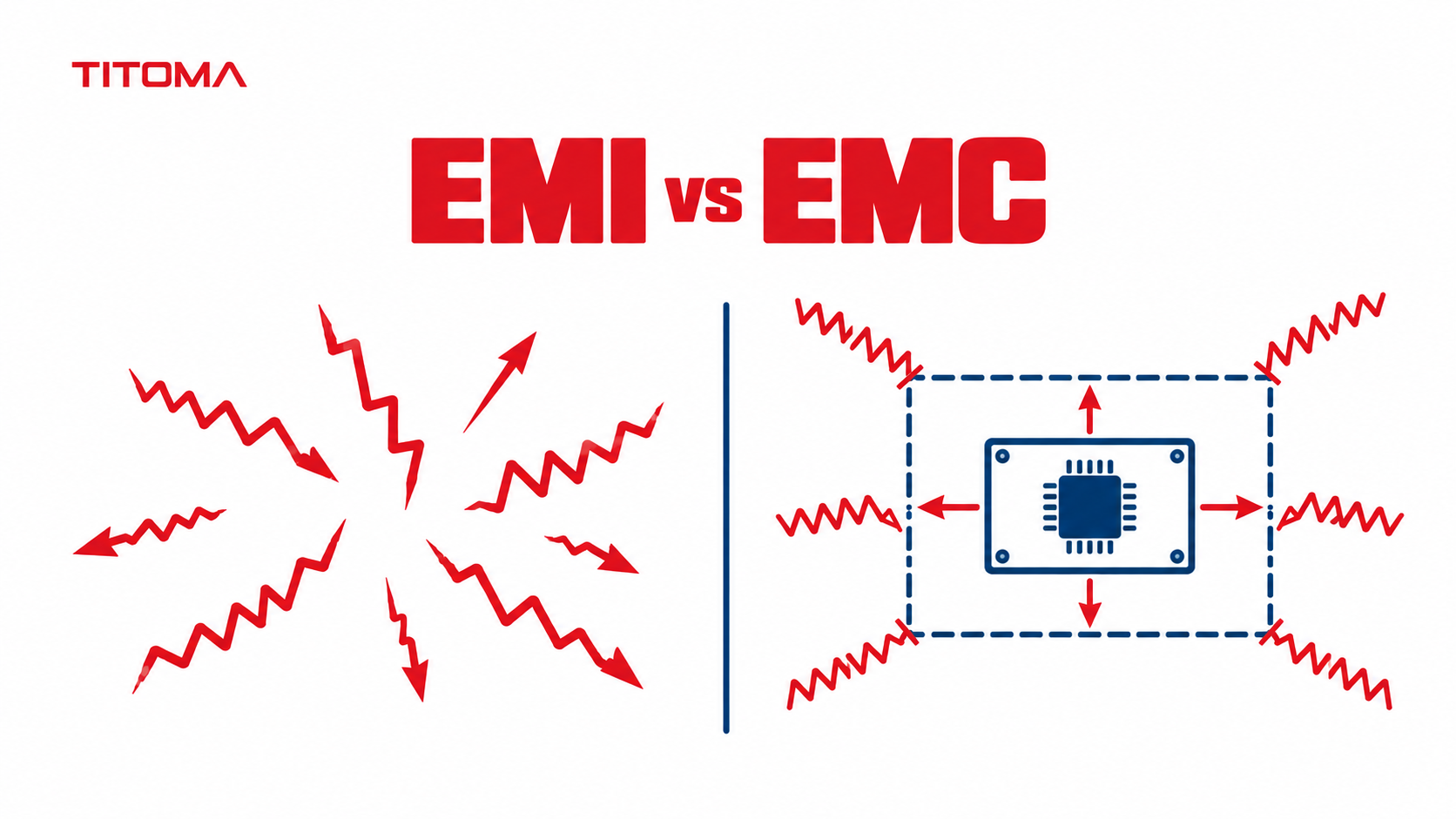
Electromagnetic interference (EMI) is unwanted electromagnetic noise that disrupts electronic devices. Electromagnetic compatibility (EMC) is a device’s ability to work correctly in its environment without emitting too much EMI or being disrupted by it. EMI is the problem; EMC is the design goal and the standard products are tested against.
EMI vs EMC at a Glance
| Factor | EMI | EMC |
|---|---|---|
| What it is | Unwanted electromagnetic noise | The ability of equipment to coexist in its intended electromagnetic environment |
| Direction | A problem a product causes or receives | Control of both emissions and immunity |
| Measurements | Conducted and radiated emissions | Emissions plus immunity tests such as ESD, surge, RF, and EFT |
| Regulatory context | FCC Part 15 limits and relevant EU emissions standards | Applicable CE EMC requirements, plus the emissions rules required in the target market |
| Typical fixes | Filtering, shielding, grounding, return-path control, and layout changes | System-level design across the PCB, cables, enclosure, power supply, interfaces, and firmware |
The terms are closely related, but they are not interchangeable. EMI describes a disturbance. EMC describes the product behavior you need after controlling that disturbance and making the product resistant to disturbances around it.
This distinction matters during product development. A team can reduce one obvious noise peak and still have an EMC failure waiting in a cable, enclosure seam, power input, or firmware state that was not exercised during the first test.
What Does EMI Cover?
EMI covers electromagnetic energy that reaches a circuit or leaves it through an unintended path. The source may be inside the product, such as a switch-mode power supply, clock, motor driver, relay, or high-speed digital interface. It may also come from outside, including radios, nearby machinery, mains transients, or another product in the same cabinet.
Engineers usually describe EMI by how the energy travels:
- Conducted EMI travels along wires, PCB traces, power inputs, grounds, or signal cables.
- Radiated EMI travels through space as an electromagnetic field, often using a cable, PCB loop, or enclosure opening as an antenna.
- Common-mode noise appears in the same direction on multiple conductors relative to a reference and is a frequent cause of cable radiation.
- Differential-mode noise appears between conductors in a pair and is often tied to switching current loops.
An EMI investigation therefore looks for a source, a coupling path, and a victim. Removing any one of those can solve the symptom. The practical difficulty is finding which path dominates in the assembled product rather than on a bare PCB sitting neatly on a bench.
Emissions testing measures noise leaving the product. Conducted emissions are commonly measured at power or telecom ports, while radiated emissions are measured with antennas in a controlled site. Pre-compliance probes and current clamps help locate likely sources, but they do not replace the final test setup defined by the applicable standard.
What Does EMC Cover That EMI Doesn’t?
EMC covers emissions and immunity as a system. Emissions ask whether the product disturbs other equipment. Immunity asks whether the product continues to operate acceptably when exposed to disturbances it should reasonably encounter.
The European Commission’s EMC Directive guidance describes both sides: equipment should not generate excessive electromagnetic disturbance and should have enough immunity to operate as intended. The exact test methods and limits come from the standards applicable to the product, its ports, and its intended environment.
| EMC test family | What it simulates | Common failure symptom |
|---|---|---|
| Radiated RF immunity | Nearby transmitters and RF fields | False readings, resets, communication errors |
| Conducted RF immunity | RF coupled onto cables | Interface errors or unstable analog measurements |
| ESD | Static discharge from a person or object | Reset, latch-up, damaged interface, frozen display |
| EFT or burst | Fast switching transients from inductive loads | Intermittent resets or corrupted data |
| Surge | Higher-energy transients on power and long cables | Protection damage or power-supply shutdown |
| Voltage dips and interruptions | Short mains disturbances | Unexpected reboot or loss of state |
EMC also includes the acceptance criteria for each test. A momentary display flicker may be allowed for one product and unacceptable for another. A safety controller, medical device, industrial gateway, and consumer accessory do not share the same operating risks. Teams should define critical functions and acceptable recovery behavior before testing starts.
Why Doesn’t Passing an Emissions Test Mean You Pass EMC?
Passing an emissions test shows that measured noise stayed below specified limits under the tested operating modes. It says little about how the product behaves when an external field, static discharge, surge, or burst enters through its enclosure or cables.
A product can be quiet and fragile. For example, careful filtering may keep a microcontroller board below radiated emissions limits, while an exposed connector lets an ESD pulse reset that same microcontroller. The emissions result remains valid, but the product may fail its immunity test within seconds.
The reverse is also possible. A metal enclosure and good transient protection can make a product tolerant of external disturbances, while a display cable or DC lead radiates a clock harmonic above the limit. Immunity and emissions share design techniques, but neither result proves the other.
Market requirements make the distinction more visible. In the United States, FCC Part 15 focuses mainly on radio-frequency emissions from covered devices. For many products sold in the EU, the EMC assessment used for CE marking includes both emissions and immunity. The practical differences are covered in more detail in FCC vs CE vs UL.
Test setup also matters. Cable length, grounding, port loading, firmware activity, radio state, power source, and enclosure configuration can change the result. A low-noise idle mode is not a useful test condition if the product normally transmits data, drives a motor, or refreshes a display under load.
How This Affects Your Manufacturing Partner Selection
An electronics manufacturing partner does not replace an accredited EMC laboratory, but it can determine whether your design reaches the lab in a testable state. The partner should treat EMC as a product requirement that affects component choices, PCB layout, cable assemblies, enclosure details, production changes, and test coverage.
Before selecting a partner or releasing a design for mass production, ask for evidence in these areas:
- Applicable standards: Can the team identify likely emissions and immunity standards for your product category and sales markets?
- Operating modes: Is there a written test matrix covering worst-case loads, cable configurations, radio states, and firmware functions?
- Design review: Does the review cover return paths, layer stack-up, filter placement, connector protection, cable exits, and enclosure bonding?
- Pre-compliance access: Can the partner arrange scans or bench checks early enough to change the PCB without losing the production schedule?
- Component control: Are filters, oscillators, power modules, displays, cables, and substitutes controlled through the bill of materials and change process?
- Failure ownership: Who captures the failure conditions, reviews lab plots, implements fixes, and confirms that changes do not create a new problem?
EMC work should start during design for manufacturing, while the stack-up, placement, filters, enclosure, and cable interfaces can still change. Waiting until a finished unit fails at the lab usually converts a small layout decision into another PCB revision, new samples, and a second test booking.
Titoma handles EMC-related design decisions as part of the electronics and manufacturing handoff, including PCB reviews, component control, prototype builds, and coordination with external test laboratories. The useful output is not a promise that a circuit looks quiet. It is a traceable set of requirements, test modes, design decisions, and production controls that can survive later component or supplier changes.
One final purchasing detail is easy to miss: ask whether the quoted price includes pre-compliance work, lab samples, extra cable sets, engineering time for failure analysis, and repeat testing. A cheap first test is not cheap when the project requires two redesigns and a delayed launch.
Keep the lab report tied to the tested hardware revision, firmware version, cable list, power supply, and configuration photographs. If production later changes a clock source, filter, cable, enclosure coating, or power module, review the EMC impact before approving the substitution. A compliant prototype is useful evidence only when production continues to match what the laboratory tested.
