
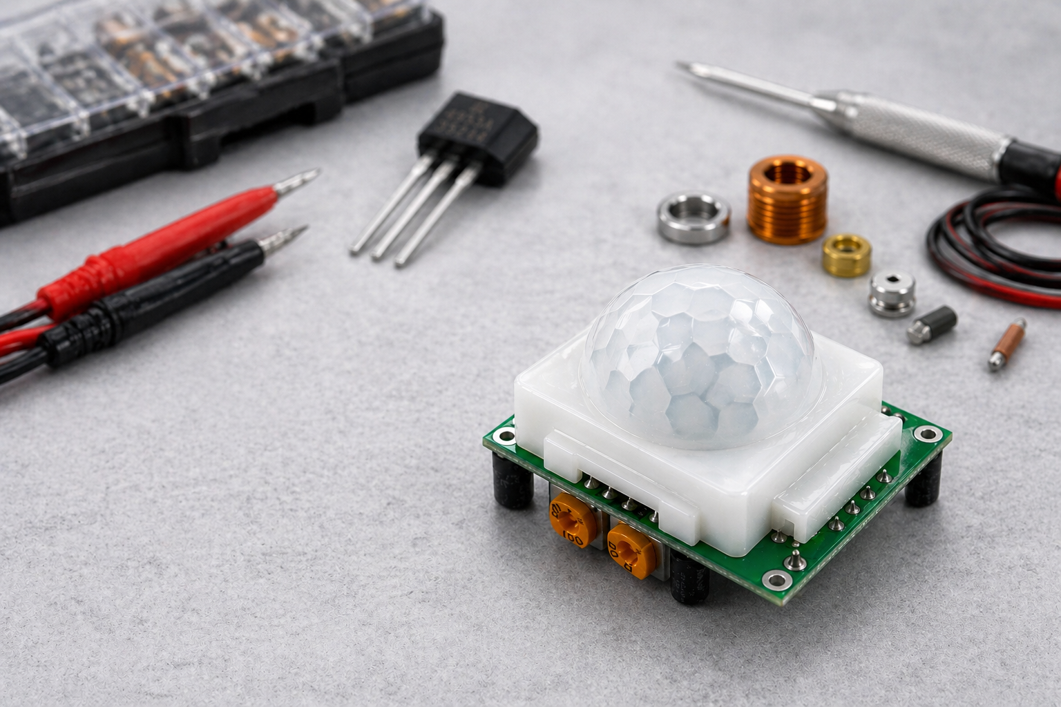
A PIR motion sensor looks simple on paper.
Detect movement. Trigger a light, alarm, or device. Move on.
In real products, it is not that clean. A PIR design that works in a prototype can still turn into false triggers, dead zones, poor detection range, awkward enclosure compromises, or unstable field performance once the product moves toward mass production.
That is why PIR sensor selection should not start with the part number. It should start with the product.
What a PIR sensor actually detects
A PIR sensor does not detect motion directly. It detects changes in infrared energy from objects with a temperature different from the background. The sensor output is a small AC signal, and the signal only appears when that thermal pattern changes across its field of view.
That also explains why PIR sensors can be frustrating in real products. They are not seeing motion in the abstract. They are reacting to thermal contrast, optics, and signal conditioning all at once.
Before choosing a PIR sensor, it helps to step back and look at where it fits in the wider sensor landscape. Titoma covered that in The 6 Essential Sensors Every Engineer Must Know. The harder part starts after that, when the sensor has to survive enclosure changes, field conditions, and real production variation.
Start with the use case, not the sensor catalog
Before choosing a PIR sensor, define what the product is trying to detect.
A ceiling occupancy sensor for lighting control has a different job from a battery-powered outdoor alarm, a smart doorbell, or a pet-immune indoor detector.
That matters because PIR selection is really a system decision. Range, field of view, lens pattern, false trigger tolerance, standby current, and enclosure geometry all depend on what the product is supposed to do in the real world.
The lens matters more than many teams expect
A lot of teams focus on the sensor element and forget the optics.
That is a mistake.
The Fresnel lens is not just a plastic cover. It creates the detection zones and focuses infrared energy onto the sensing elements. Without the right lens, the sensor cannot build a useful field of view.
In practice, the lens often decides whether the detector behaves well or badly in the final product. It affects coverage angle, zone shape, sensitivity, blind spots, and how much unwanted movement gets through.
So if a team chooses a PIR sensor without locking the lens and enclosure concept early, they are only doing half the job.
False triggers are usually a design problem, not bad luck
This is where PIR products often go wrong.
A PIR sensor that triggers on HVAC airflow, sunlight shifts, pets, reflections, or background thermal noise is not too sensitive. It is usually part of a badly balanced system.
False alarms are not just firmware problems. They start with sensor choice, lens choice, placement, and analog front-end behavior.
For mass production, this matters a lot. A design that produces nuisance triggers in the field does not feel slightly wrong. It feels broken.
Placement and enclosure decide whether the sensor still works
A PIR sensor may look fine on the schematic and still fail once it is installed in the real product.
Mounting height changes coverage. Enclosure openings change the field of view. Plastic windows, filters, nearby heat sources, and internal airflow all affect what the sensor sees.
That is why PIR sensors should always be validated in the real enclosure, not just on a lab bench. Bench success proves the electronics work. It does not prove the product works.
That is why PIR selection should not be treated as an isolated electronics choice. Titoma makes the same broader point in its article on how design for manufacturing reduces cost. If the optics, enclosure opening, PCB layout, and test approach are left disconnected, the product may still work on the bench and quietly become expensive in production.
Power budget and signal chain are part of the sensor choice
PIR is popular partly because it can be low power, which is why it shows up so often in battery products. But low power only helps if the whole signal chain is designed properly.
The raw PIR output is tiny, so amplification and conditioning are essential. Weak analog design, noisy layout, or unstable thresholding can turn a decent sensor into a weak product.
In a prototype, engineers can tune around this. In production, every extra tweak becomes cost, time, or support burden.
What to check before locking in a PIR sensor
For mass production, the right PIR sensor is usually the one that balances five things well.
- Detection behavior, including coverage and range
- Lens and optics compatibility
- False trigger performance in the real environment
- Power consumption and signal-chain stability
- Mechanical fit inside the enclosure
Teams should also check sourcing depth, package consistency, and whether the chosen part is supported by realistic second-source or redesign paths. A sensor that performs well but is awkward to source or too sensitive to assembly variation is not a strong production choice.
Teams should also be careful not to lock in a PIR sensor too early just because the first prototype seems fine. Titoma’s article on questions to answer before starting your DFM is relevant here because the same early design decisions that look harmless in EVT can turn into sourcing, yield, or reliability problems later if no one checks the system around the part.
Final thought
Choosing a PIR motion sensor for mass production is not just about finding a sensor that can detect movement.
It is about choosing a sensing system that still behaves properly once optics, enclosure, ambient conditions, analog design, and production variation all show up at the same time.
That is why the best PIR choice is rarely the one with the nicest looking datasheet.
It is the one that still works when the product leaves the bench and starts repeating at scale.