
IR obstacle sensors are cheap, useful, and annoyingly easy to kill.
The problem is not usually the IR LED, photodiode, comparator, or the small trimpot on the board. The problem is simpler: the pinout is not always the same.
Many IR sensor modules use three pins: GND, VCC, and OUT. Some boards label the output pin as IR, S, DO, or Signal. That sounds simple until you buy modules from a different supplier and the pin order changes.
Same-looking black PCB. Same blue trimpot. Same 3-pin header. Different wiring.
That is how a five-cent assumption becomes a dead sensor, a damaged GPIO pin, or a prototype that “worked yesterday.” It is also why pinout control belongs in the same conversation as design for manufacturing, not just in the lab notebook.
What an IR Sensor Module Usually Does
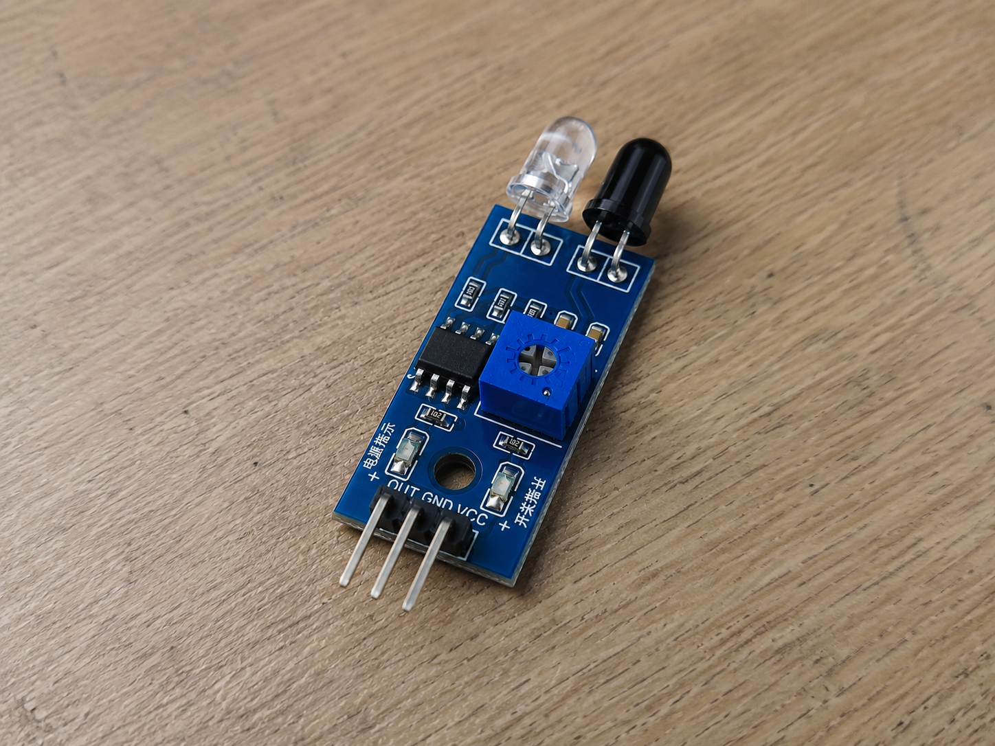
Most small IR obstacle sensor modules combine an infrared LED, a receiver, and a comparator circuit. The IR LED sends out infrared light. When an object reflects enough light back to the receiver, the circuit switches the output pin.
A microcontroller such as an Arduino, ESP32, STM32, or Raspberry Pi Pico reads that output.
In simple projects, this works fine for obstacle detection, line sensing, object counting, or basic presence detection.
In real products, the same module-style design has limits. Ambient light, surface color, distance, angle, dust, enclosure windows, and mechanical alignment all affect readings. Optical sensing looks simple on a bench and then becomes much less charming once the enclosure, cable, and production variation show up.
The pinout is just the first thing that can go wrong. Sadly, it is also one of the easiest things to prevent.
The Three Pins You Normally See
Most IR sensor modules have these pins:
GND
This connects to the system ground.
No shared ground, no reliable signal. That part is not optional.
VCC or 5V
This powers the module.
Many boards are sold as “3.3V to 5V” or “5V compatible,” but do not assume that from the listing photo. Some cheap modules use parts that behave differently at 3.3V, especially when the output stage, comparator threshold, or onboard LED current is marginal.
OUT, S, Signal, or IR
This is the output pin that connects to the microcontroller input.
Some modules output a digital signal. Others may expose an analog-like signal depending on the board design. Check before designing firmware around it. Guessing is not engineering, though it is a popular hobby.
Four Common IR Sensor Pinout Layouts
The image shows four pinout variations. These are worth checking because modules from different sellers may use different header orders.
Type 1: GND, 5V, IR, GND
This version has four pins:
GND | 5V | IR | GND
The extra ground pin may be included for convenience, layout symmetry, or signal stability. It is not unusual to see duplicated ground connections on small modules.
From a product design point of view, this can be useful if the module connects through a cable and you want a better ground reference. But it also creates confusion during assembly if the connector is not keyed or clearly marked.
If this module gets swapped with a 3-pin version during sourcing, the cable harness may no longer match. That is a small purchasing change with a very real failure mode.
Type 2: IR, 5V, GND
This version uses:
IR | 5V | GND
This layout is dangerous because it may look like a normal 3-pin sensor, but the signal and ground positions are reversed compared with other common boards.
If a technician or hobbyist assumes the left pin is ground, the module may be connected incorrectly. In the best case, it simply does not work. In the worse case, VCC ends up where it should not, and the module dies quietly.
No smoke, no drama, just another “bad batch” that was not actually bad.
For production, this is exactly why visual similarity is not enough for incoming inspection. The same logic applies across many common PCB components: the part may look familiar, but the footprint, rating, tolerance, or pinout still needs to be verified.
Type 3: GND, 5V, IR
This is one of the more common layouts:
GND | 5V | IR
Many Arduino-style IR obstacle sensors use this order. It feels familiar, which is also the trap.
Once a team gets used to one layout, they often build cable harnesses, test jigs, and assembly instructions around it. Then purchasing finds an alternate supplier with the “same” module, and suddenly the pinout is different.
This is not a component problem. It is a documentation and sourcing control problem.
Type 4: IR, GND, 5V
This version uses:
IR | GND | 5V
This is less common, but it shows up often enough to matter.
The main risk is that VCC and signal positions do not match the expected cable order. If the module is plugged into a fixture designed for another pinout, the test may fail immediately or damage the board under test.
For prototypes, this is annoying. For production, it burns time. Someone has to stop the line, check whether the sensor is bad, check the fixture, check the cable, check the firmware, and eventually discover the module was wired differently.
Excellent use of everyone’s afternoon.
Why Wrong Wiring Can Damage More Than the Sensor
A bad IR sensor connection can cause several problems:
- Power and ground can be reversed.
- The output pin can be forced to a voltage it was not designed to handle.
- A microcontroller GPIO can be exposed to 5V when it only tolerates 3.3V.
- A short can overload the module, controller board, USB port, or bench supply.
- The sensor may still power on, but give unstable readings.
That last one is the worst. A fully dead module is easy to debug. An unstable module wastes time because it looks like a firmware issue, lighting issue, threshold issue, or mechanical issue.
What to Check Before Wiring an IR Sensor Module
Start with the boring checks. Boring checks save boards.
- Read the silkscreen on the PCB. Do not trust the product photo alone.
- Check the seller’s datasheet or pinout diagram. If there is no datasheet, treat the part as a risk, not a bargain.
- Use a multimeter to identify ground if the labels are unclear.
- Check whether the output is 3.3V-safe before connecting it to an ESP32 or other low-voltage controller.
- Use current-limited power during first bring-up.
- Use keyed connectors where possible.
Ground often connects to large copper pours, mounting holes, or the negative side of decoupling capacitors. That is not a replacement for documentation, but it helps when the board has the labeling quality of a mystery snack from a night market.
What This Means for Product Design
Using off-the-shelf IR modules is fine during early prototyping. They are cheap, available, and fast to test.
But they are not automatically a good production choice.
For a real product, the team should decide whether to keep the module or move the circuit onto the main PCB. That decision depends on volume, enclosure constraints, optical alignment, cost target, supply stability, and test strategy.
A module may be faster at low volume. A custom PCB may be better when you need controlled connector placement, reliable sourcing, stable optical geometry, and a proper production test plan. This is the same tradeoff covered in Titoma’s article on module vs custom PCB design for new products.
Neither option is magically better. The wrong choice just fails in a different department.
Production Risks Teams Often Miss
The biggest risk is not that one engineer wires one sensor wrong. That happens and gets fixed.
The bigger risk is uncontrolled variation.
- One supplier ships GND, 5V, OUT.
- Another ships OUT, 5V, GND.
- A third changes the PCB revision without telling you.
- The purchasing team sees the same product title and approves the substitution.
- The assembly team plugs it into the same harness.
- The test team sees failures.
- Engineering gets blamed, because tradition must be respected.
This is why even simple modules need proper part numbers, approved vendors, photos, pinout drawings, and incoming inspection criteria.
A working prototype is not the same as a controlled production design. Before mass production, the factory will care about sourcing, assembly, testing, and repeatability. Titoma covers that broader handoff problem in its guide on how to approach a manufacturer for mass-production.
Practical DFM Advice
If the IR sensor stays as a separate module, define the connector pinout clearly in the assembly drawing.
- Use keyed connectors instead of loose Dupont wires.
- Add reverse-polarity protection if the module may be connected manually.
- Add series resistance or input protection on the signal line if the controller pin is sensitive.
- Define voltage levels clearly, especially when mixing 5V modules with 3.3V microcontrollers.
- Add a simple production test that confirms sensor output changes when an object is placed at a known distance.
If the sensor is moved onto your own PCB, leave room for optical alignment, mechanical tolerance, and test access. The electronics may be simple. The physical setup usually is not.
This is where a proper PCB DFM review helps. It catches connector orientation, test access, layout, assembly, and sourcing problems before they turn into factory-side entertainment.
Final Takeaway
IR sensor modules are useful, but the pinout is not universal.
Before wiring one, check the PCB label, datasheet, seller documentation, and voltage compatibility. Before using one in production, control the supplier, connector, cable, and test process.
A burned module is cheap.
A batch of products built around the wrong assumption is not.